Showing posts with label Display. Show all posts

Tuesday, May 1, 2018

SPEBEG (Single Player Eight Bit Electronic Game)

Finally got around to finishing the last details of an old shcool project.
A simple 8bit game, aim with the joystick at the target and fire! Increase points and try to keep up with the increasing speed!


Here is a pretty much self explanatory video of the device.

The concept is pretty simple and the building blocks only required a little dab of logic glue and some filtering to get it up and running.

Starting from the Power Supply block it's a normal full bridge rectifier and a classic 7805 linear regulator. As the game needs a bit of randomness I decided to use the rectified input for a 100Hz clock. This clock is stable over long periods of time but has minor changes and this is where I'm getting the little bit of randomness. The 100Hz clock also handles the LED matrix time multiplexing between the User Input and the Target Generator blocks.

The secondary clock is provided by the venerable 555 IC pumping away at about 47KHz. This clock is fed into the Target Generator block.

The Target Generator block is based on 74190 BCD counters fed into 7442 Selectors. The end effect is a continued scanning of the LED matrix on the bus. This bus is fed into 74373 Latches that are triggered from the Delay block.

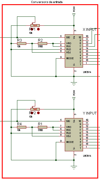
The Analog Input block are a pair of LM3914 bargraph drivers in dot mode and spitting out the result onto the 8bit bus.


A close up of the Power Supply, Secondary Timer, Analog Input and two thirds of the Target Generator blocks as well as the power input and joystic input.

The Delay block are another set of 74190 BCD counters set as frequency dividers for the 100Hz clock. The counters are loaded with the current score value so the higher the score the shorter the count delay and thus the game speeds up. There are four levels available. I have not scored much higher than 22 points on the lowest level...

The Delay block output is passed through a delay filter with clamps that then goes back to the Target Generator block to load the input of the 74373 latches onto the 8bit bus.

The Scoring block is yet again... more 74190 BCD counters fed into 7448 BCD to 7 segment display drivers. The input is provide via the Control Logic block.

The Comparator block simply compares the 8bit Analog Input and Target Generator buses with a pair of 74688 comparators and when triggered by the Fire button on the joystick send out a matching or not signal to the Control Logic block.

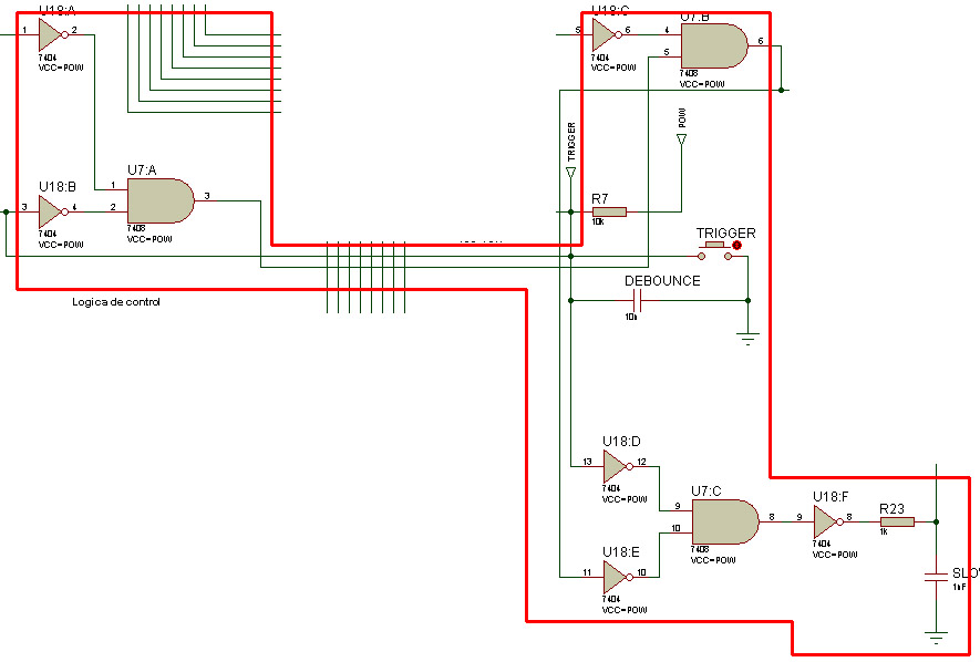
The Control Logic block is that dab of glue that holds it all together. In order to keep parts count down and use as less variety of IC's possible a classic 7404 NOT and 7408 AND gates were used.
The left (U7:A) AND gate will send a logic 1 when the trigger is pressed (logic 0) and the X comparator inputs match (another logic 0). The righ (U7:B) AND gate receives the logic 1 and again if the Y comparator inputs match will also output a logic 1.
The trigger and AND output is sent to the lower right (U7:C) after being inverted. If the user misses the target the output will reset the Scoring block and thus the Delay block will also reset to the maximum delay, the easiest speed.

The Bus Selector block handles what bus to send to the LED matrix with four 74157 demultiplexers, either the User Input or the Target Generator 8bit bus. This is handled from the 100Hz clock divided by two to get a 50% duty square wave.

The LED matrix display is driven with a 74540 and 74541 octal line drivers.

A closer view at the IC's.

The simple LED matrix and 7-Segment displays.

The ratsnest of point to point wiring with enameled wire.

The reason I bought my first temperature controled soldering station... Needed a fine tip with enough temperature to remove the enamel on the wire.

I'd never done point-to-point Wire Wrapping wiring like this, I tried to keep it tidy but the deadline was very close and the staggering 200€ worth of (localy sourced) IC's and long pin sockets really kept me going to get it finished. It worked in time : ) but had a few minor flaws that rendered it very hard to play : ( About 5 years later I dug it out and fixed all the issues. Back to storage it goes!

Well, thanks for reading. I'm going to try to update this blog a bit more frequently and actually finish projects instead of just leaving them as a proof of concepts.

Read More!

Saturday, December 5, 2009

Detolf Lighting

Here is a small guide to my still incomplete Detolf RGB LED lighting!


This is my nearly complete lighting setup. It consists of Ikea Dioder RGB LED lighting strips controlled by a micro controller that sets the RGB color.
So not only do I get lights off and lights on;


I can get Red, Green and Blue!


And I can also combine RGB to produce lots of other colors;


Also, the colors can be programed to follow certain patterns and effects thanks to the MoMoLight hardware/software and the BobLight software.
My version has slightly different hardware, firmware and a software color controller.
It's not pretty, but it works for what I need;

The whole setup can work as an ambient mood light, gently fading from one color to the next, or pulse violently at the rhythm of music.
Installing the Dioders into the cabinets is simple, but the wiring is a bit tricky, here are a few pictures of how I put mine together, its not permanent and is held together with tie wraps!


My goal is to get each Detolf shelf LED strip to be controllable individually as right now it only has 3 channels. Although I'm using a programable micro controller you can still have multicolored goodness with the standard Dioder controller.
If you have any questions please ask away!

Read More!